In this second part of The Making Of Mortimer, I’ll be talking about the mechanics and programming that went into making the physical manifestation of our chatbot actually tick.
As I mentioned in the entry on Mortimer’s personality, we got an early start on our chatbot. We narrowed down the object we wanted to a clock in the second week of the semester, and by September 9th, we already had an actual clock to work on.

We also had to work on ideas for the rooms during week 2, which is why I made a 3D representation of the Kitchen space as a rough estimate to get a feeling for what our room could be like. We were hoping one of the spaces would be a kitchen because the ideas we had for the dialogue involved our bot helping the user learn how to cook. We showed the model to the class after our presentation and it helped us narrow down the list of ideas to a Bathroom, a Living room and a Kitchen, as we’d hoped.

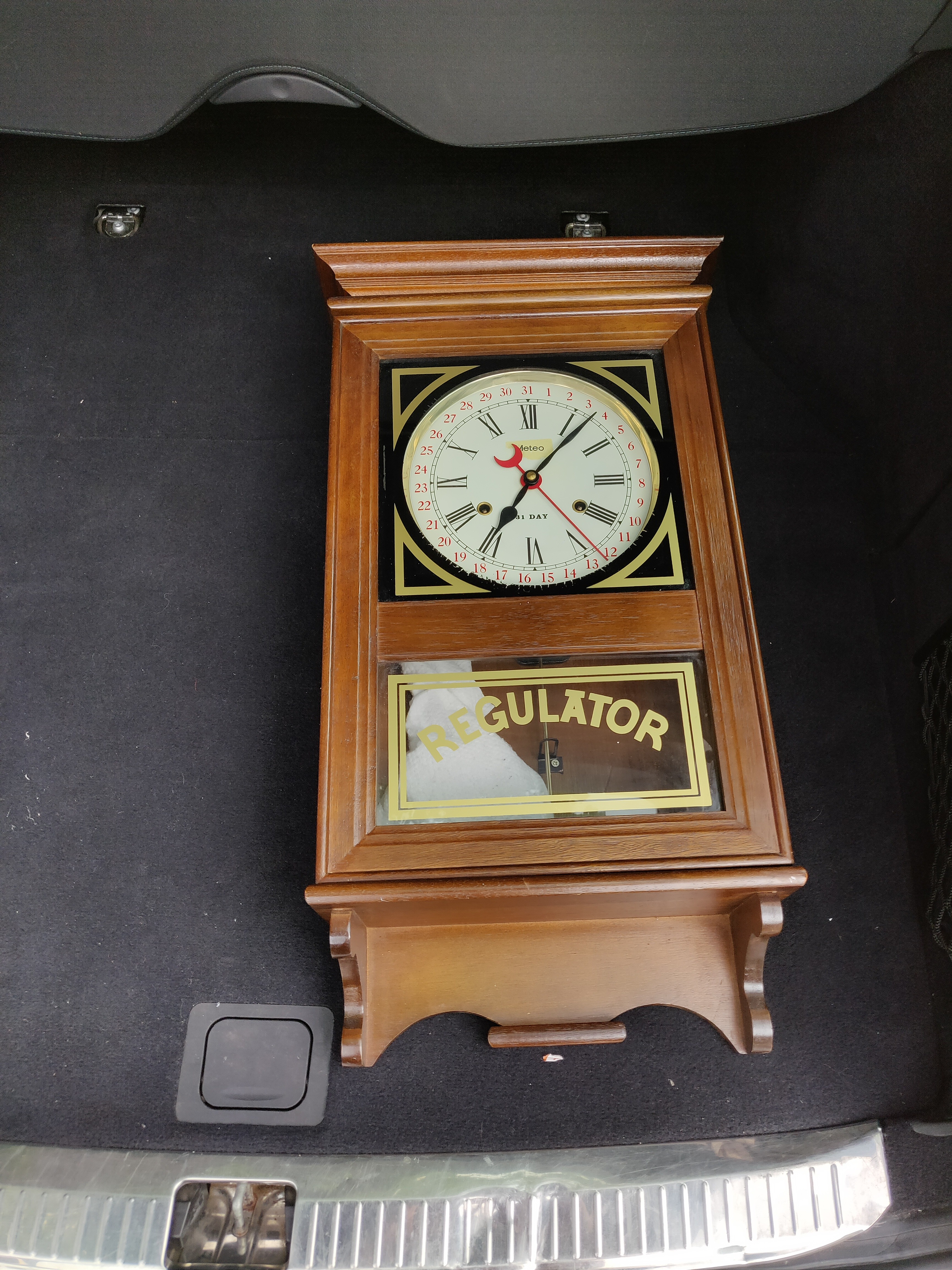
Going in without any knowledge of the internals of the clock, our initial plan was to integrate a screen behind the glass panel near the bottom. We would then use that to show emotions and perhaps even a simplified face when the clock would be talking, and relevant information like recipes, the weather, and other such things when needed. The feedback we got however, indicated that we probably shouldn’t integrate an actual screen into the object but rather keep things more subtle. That’s when we looked into integrating LED strips instead. I proposed we’d keep it simple and just run the current of the audio through it to make it pulse with the sound, and Ignas went ahead and realized that idea:
However, as we quickly realized, a lot of other groups were making their objects light up with leds, so we wanted to do something more original. We decided to drop the leds idea and work on making the hands of the clock turn around. This was also around the time when we got some negative feedback on the aesthetics of our clock, so we decided to purchase one that was a bit more modern, but still had an aged vibe to it. We did our research looking into all kinds of clocks, and ended up going to an Action store to get this clock:
This clock has been the work-in-progress prototype clock for the majority of the project. It had a simple, standard battery powered motor on the back and it’s open back design allowed us to easily experiment with it.

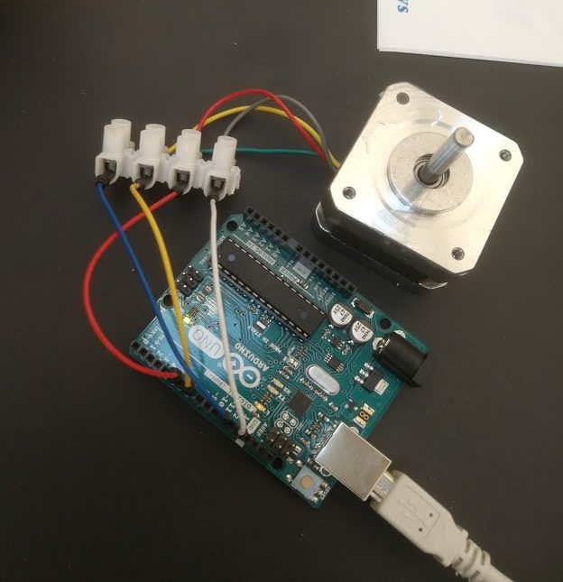
I had no previous experience working with Arduino, and I didn’t think I’d ever get another chance to work with one without actually having to commit to buying one myself so I decided to take charge of making the clock actually tick. It didn’t take too long to get the motor spinning. I had a basic turn cycle thing set up in less than a week. That, as it turned out, was the easy part.
Then came down to actually controlling the arduino and motor from another device. I looked into serial communication via USB. The end goal was to make it able to be controlled by the Raspberry Pi we’d use as a backend server for our Google Home. After a while of finding and testing code samples from the internet, I reverse engineered one to a level where I could use it to send simple commands to the Arduino, which the Arduino would then use to change the direction or speed of the motor. Due to some limitations though, it would only process one character of a sent string at a time. It later turned out that if I tried to make it take the entire string, it’d delay everything on the arduino and stop the motor until the entire string was read into its memory.
I decided to use this bug as a feature, and implemented a basic system I dubbed ‘moodcodes’ in order to control the clock. A moodcode would be a string of directions that the clock would follow one by one. ‘L’ would stand for turning left, ‘R’ would stand for turning right, ‘0’ would stop it and ‘1’,’2′ and ‘3’ would be 3 different speeds for it to turn. There was an additional character, ‘D’, that would provide a certain amount of milliseconds delay before the next action would be executed, but timing was later moved to the Raspberry Pi as part of moodcodes 2.0. An example of an early moodcode would be “L3DDDR1”, this would turn the motor counter-clockwise at max speed and then after 3 delays turn clockwise at the lowest speed. This solution was a quick and dirty – throw it over the fence and let the arduino handle it – solution. It turns out, however, that this was not going to work. There was no way to properly stop this during a moodcode’s execution as any other commands sent would be queued onto it instead of interrupt it. We quite literally went back to the drawing board.
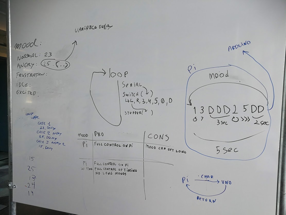
The solution I came up with was two-fold. We’d have to move most of the moodcode processing to the Raspberry Pi, with the Arduino simply executing parts of the moodcode as they arrived. While we knew that had to be done, there was still the issue of the delay. The new plan was initially to still run a delay on the Arduino itself. The idea was to wait for the Arduino to send a message back after each command on which the server would wait before sending the next command. This way we could stop sending it messages at any time. That plan was slightly altered in favor of making the delays run on the server too. This simplified things as I didn’t have to listen for incoming messages from the Arduino anymore. This did change the form of the moodcodes, though, as the new system required them to be an array of small bits of moodcode, plus the delays after each bit.
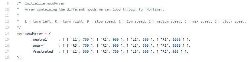
Despite not having any experience with NodeJS before, I wrote a module for our server to process the moodcodes and send them to the Arduino all through a simple function call every time Mortimer was going to say something. This seemed to all go off without a hitch until it came down to actually sending the commands via Serial. I tried all the libraries I could find, read through all the documentation – of which there wasn’t much to begin with, but it just refused to work. I could not figure out why.
At the end of my rope, I decided to look into some alternative method to at least get communication working. I attempted to get the NodeJS server to run a python script which could in fact communicate with the Arduino. Halfway through this process, however, I noticed that the documentation for Serial communication for Python was much more detailed. After looking into it I discovered that Arduino required the Serial communication to be UTF8 encoded.
I hooked up a UTF8 library to encode the commands before sending them and… it worked. We had a way to reliably control the Arduino and its motor from the NodeJS server on the Raspberry Pi.
While I was busy trying to get the motor working, Nash was working on making sure the motor could be attached to the clock. The initial plan was to use some Lego parts glued to the backside of the clock to transfer the force from the motor to the adjustment dial on the back of the clock. This plan failed, however, as Pim had glued the cogs the wrong way around making it harder for the motor to turn the clock. When we were trying to fix this, the dial broke off.
We tried a few different solutions at first. Controlling the voltage of the clock’s motor directly via the Arduino didn’t work despite following the guide I’d found to the letter, so we opted for sticking the hands directly to the clock and moving them together as one. This way we didn’t have to deal with the fragility of the clock’s motor. This worked fine for a while, until we were asked to find a new clock again.
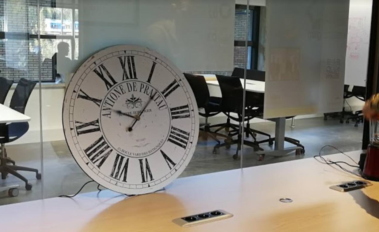
We had to find something without text on it but still something that had a retro-ish old-ish vibe to it. Nash and I looked for new clocks for days but we could not find any on second hand websites. Nash worked with Woody directly to find a new clock on the Ikea website that satisfied Woody’s requirements and wasn’t too modern for our tastes either. The Pollett clock is sleek in design but has just a touch of retro that makes it suitable for the personality we were aiming for.
There was one downside to it, however. It wasn’t flat. This meant we couldn’t easily mount the motor to the back of the clock anymore. We were also approached by Wouter, who wanted to help us get the clock working by powering it with the motor directly. I objected to this plan listing quite a few things that could go wrong; The adjustment dial could break off, the teeth on the cogs inside could break off because of too much force or speed, the alignment of the motor could be off and it could come loose, the glue might not stick or, quite simply, the motor wouldn’t stay attached properly. Despite voicing my concerns, the plan went through as we had to try, according to Wouter. He got us a 3D printer and helped Nash print some parts to make it all connect.
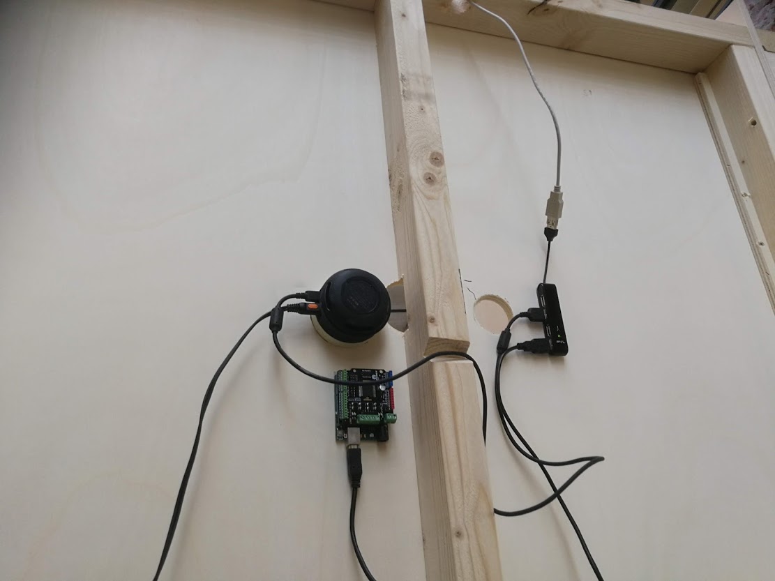
Initially, it appeared to be working. Everything came together perfectly on Tuesday. We hung the clock on the wall in the Kitchen space, stuck the Arduino on the inside of the wall, attached everything properly, and tested it quite a few times over the day to make sure it worked alright. I then went back upstairs to work on writing my own motion sensor code as the code we’d been promised by Geert Jan wasn’t sent to us until 12 AM on Wednesday, which would be after the wall were said to be closed up. While I was working on integrating the motion sensor to the Arduino, it turns out the clock started acting up and stopped turning properly.
When I arrived on Wednesday, it had stopped responding almost altogether. I was not aware of the issue until the walls of the Kitchen space were closed off. I spent the whole day till 16:30 trying to get it working again, well after everyone had gone home. I had identified the main issue and had attempted a fix.
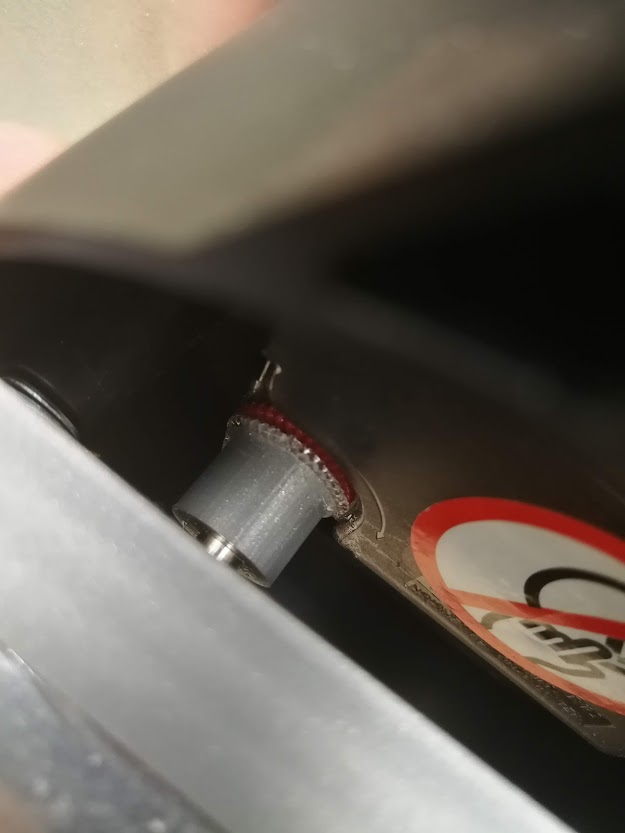

It turned out the glue that held the adapter piece between the motor and the adjustment dial attached to the adjustment dial had come loose. The dial had not been sanded, so the glue never properly adhered to it. When the glue had finally fully set, it lost its stickiness and could no longer transfer the rotation of the motor to the adjustment dial. This was why it had failed. However, in trying to find out what went wrong, I likely caused a cable to break inside the wall. The motor was dead in the water. We couldn’t cut into the wall without risking cutting into more cables, or the Arduino itself. We had no way of fixing it.
Two days later, however, I came up with an alternative solution. We could, in theory, hook up another Arduino. I knew we had put my USB hub next to an existing hole behind the clock, we could hook it up to the Raspberry Pi that way and then hide it behind the clock after all. After spending several hours trying to get this to work however, we came to the conclusion that for some reason or another, we couldn’t communicate with two Arduinos at once from the Raspberry Pi. We could either make the clock or the motion sensor work. We chose the motion sensor.
If there’s anything I’ve learned from this entire process, it might be to make sure to have a better back-up plan. Or to plan ahead better to avoid these situations. Or to test the final product more before moving on to the next part. It might even be to stand my ground when I know something is a weak link in the plan and that we shouldn’t do it that way.
There’s a lot of things I have a lot of critique on in the process of making this clock work. I got my part working as promised, but while I was working on that I should’ve kept track of how the clock itself was being built as well.
In that regard, we didn’t really have anyone managing the project. We worked together alright enough, so we didn’t really need one. But I do wonder if some of our issues could have been avoided if we had appointed someone as project manager, or if I had stepped up to the task. I tried to lead the team a bit during the first few weeks, but that role sort of fell away when we merged the two kitchen groups.